Learn about the factors that cause pressure loss in HVAC duct systems, such as duct length, elbows, branches, cross-section, and fittings.
When designing ventilation and air conditioning systems, airflow is not the only factor to consider. Air moving through straight ducts, elbows, reducers, branches, and valves all create some resistance. If pressure losses are not adequately accounted for, the system may struggle to achieve the required airflow or the fans may have to operate in an unsuitable mode.
1. Where does pressure loss originate?
Pressure losses are typically considered in two groups: losses along the duct due to friction as air moves through the pipe, and local losses at components such as elbows, tees, reducers, valves, and air grilles. The total loss of the line is related to its length, cross-section, surface roughness, air velocity, and fitting geometry.
Therefore, simply looking at duct size or fan power will not be enough to assess the efficiency of the entire system.
2. Factors that can increase resistance
Excessively long pipelines, numerous changes in direction, abrupt changes in cross-section, or poorly designed branching can all increase losses. Modifying the pipeline route on-site without updating calculations can also lead to operating conditions different from the original design.
The cross-sectional dimensions should be selected based on the flow rate and velocity limits appropriate for the project. Do not arbitrarily increase or decrease the dimensions simply for ease of construction without confirmation from the design team.

3. Coordination between drawings, accessories, and fan selection.
The drawings should clearly show the dimensions, alignment, diversion points, and main fittings. When changing the pipe structure or route, the contractor should coordinate with the design team to assess the impact on pressure loss. This calculation data is also crucial when selecting fans and adjusting the system.
4. Summary table of influencing factors
The following table is for design review purposes only; it does not replace hydraulic calculations or manufacturer's technical data.
| Element | Potential effects | Points that need review |
| Pipeline length | Increase friction along the road. | Optimizing the route while ensuring sufficient space and maintenance. |
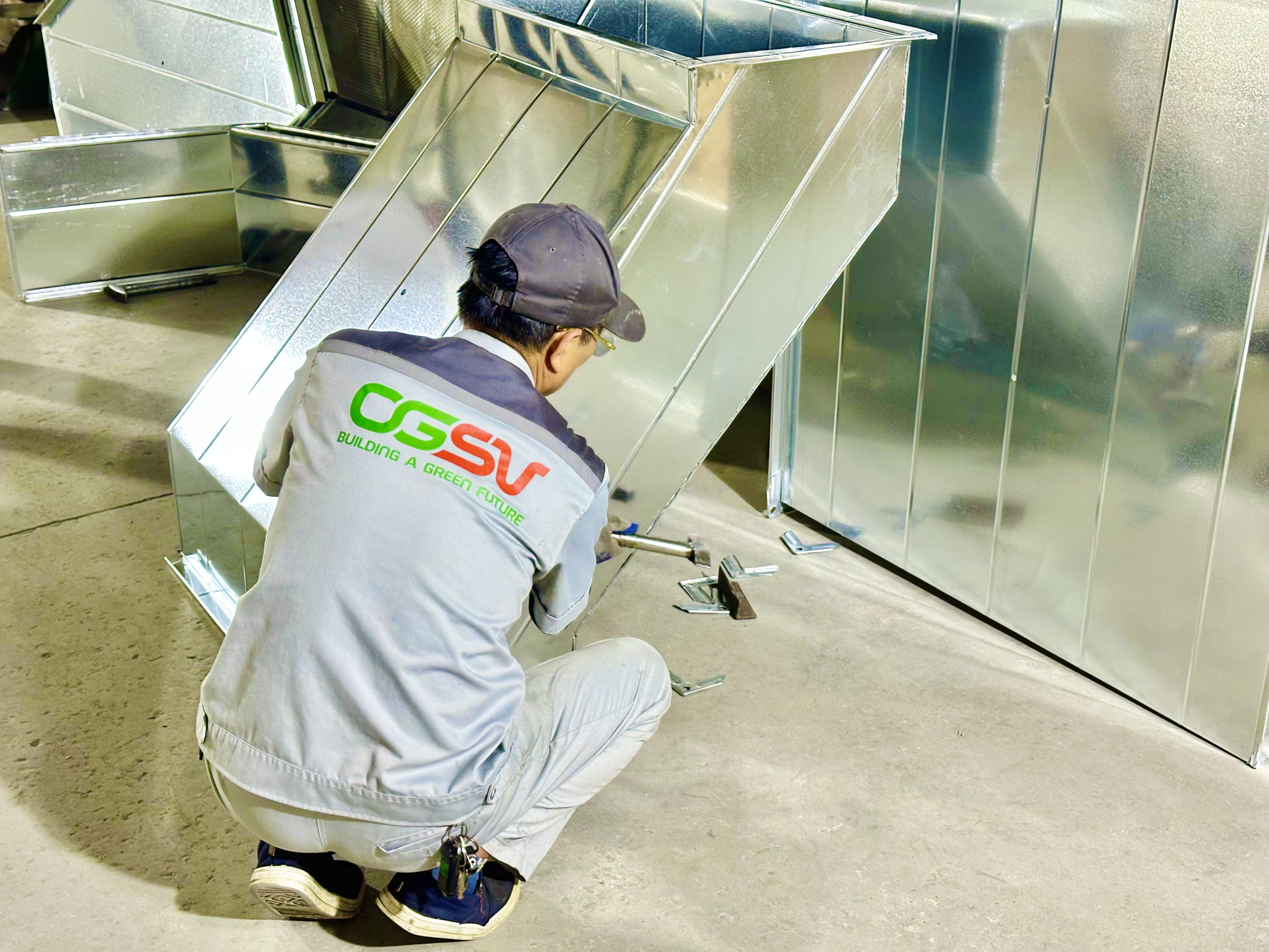
| Co, cut, numb | Creating local losses | Use the correct structure as shown in the drawing, avoiding unnecessary changes in direction. |
| Change the cross-section | It can cause sudden changes in airflow. | Check the size and shape of the cone. |
| Valves and air vents | Create resistance based on structure and operating conditions. | Compare the specifications and installation location. |
| Differences from the design | Altering the pipeline's characteristics | Update the drawings and obtain approval before construction begins. |
Conclusion
Pressure losses need to be considered from the design phase and continuously monitored during fabrication and installation. Close coordination between the design unit, M&E contractor, and manufacturer helps minimize unnecessary changes and supports the system's operation according to the set objectives.
Contact Sao Viet Air Ducting
Sao Viet Ducting provides fabrication services for square, round, spiral ducting and HVAC accessories according to technical specifications. Contractors can submit drawings to discuss the structure and scope of supply.
SAO VIET AIR DUCT MANUFACTURING AND TRADING COMPANY LIMITED
Address: 267 Le Thanh Tong, May Chai, Hai Phong
Hanoi Representative Office: No. 19, Lane 24, Kim Dong Street, Giap Bat Ward, Hoang Mai District, Hanoi
Hotline: 0815.999.826 – 0934.559.168 | Technical support: 0949.852.886
Email: vietonggio@gmail.com