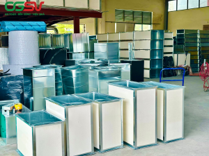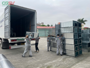
Learn about the causes of HVAC duct leaks, their impact on airflow and energy, and the points to inspect at joints, flanges, access doors, and fittings.
In HVAC systems, ductwork not only needs to be the correct size but also must meet the sealing requirements specified in the design documents. Leaks at joints or fittings can alter airflow distribution, increase fan load, and complicate system calibration. Therefore, sealing control should be considered from the design and fabrication stages to installation and commissioning.

1. Where do air duct leaks most commonly occur?
Areas requiring priority inspection include longitudinal pipe joints, joints between two pipe sections, flanges or connecting clamps, connections to dampers, inspection hatches, and equipment. At bends or branch points, incorrect geometry during assembly can also lead to poorly sealed joints.
It should not be assumed that all leaks stem from material quality. Dimensional deviations, uneven contact surfaces, insufficient or incorrect use of sealing material, as well as impacts during transportation and installation, can all be causes.
2. How does a leak affect the system?
Air leakage can result in lower-than-designed airflow to the usage areas. Fans may have to operate longer or in suboptimal modes to meet demand. For systems requiring pressure control or specific environmental conditions, inadequate sealing also makes calibration and testing more difficult.
The extent of the impact depends on the leak location, working pressure, total pipeline length, and project requirements. Therefore, the assessment should be based on the acceptance criteria specified in the technical documentation.
3. Points to check during production and installation
The actual dimensions should be compared with the drawings; check the squareness and flatness at the connectors; confirm the correct type of flanges, clamps, and sealing materials; and protect the pipe ends during assembly. During installation, avoid using force to join misaligned pipe sections, as this can cause deformation or create gaps elsewhere.
4. Duct tightness test chart
The table below is a practical checklist. Test criteria and acceptance levels must conform to the design, applicable standards, and project requirements.
| Inspection location | Content to be considered | Procedure for handling abnormalities upon detection. |
| Tube body joint | The seam is continuous, without gaps or deformation. | Check the joint and machining requirements. |
| connecting flange/clamp | Contact surface, gasket, or sealing material | Clean the surface, align it, and process it according to technical instructions. |
| Connect accessories | Correct size, correct orientation, and not pulled out of alignment. | Measure and adjust before fixing. |
| Inspection hatch, air valve | Frame, wing, and joint | Check the sealing mechanism and refer to the manufacturer's instructions. |
| After installation | Results of the inspection according to the acceptance criteria. | Record and address any non-conformities. |
Conclusion
Duct leak control should be implemented throughout the entire process, from fabrication to acceptance testing, rather than only addressing issues once the system is operational. Contractors should agree on tightness criteria, inspection methods, and scope of responsibility from the outset to minimize the need for repairs.
Contact Sao Viet Air Ducting
Sao Viet Air Ducting Company manufactures air ducts and accessories according to project drawings and technical requirements. M&E contractors can submit drawings or Bill of Quantities to discuss scope of supply and suitable solutions.
SAO VIET AIR DUCT MANUFACTURING AND TRADING COMPANY LIMITED
Address: 267 Le Thanh Tong, May Chai, Hai Phong
Hanoi Representative Office: No. 19, Lane 24, Kim Dong Street, Giap Bat Ward, Hoang Mai District, Hanoi
Hotline: 0815.999.826 – 0934.559.168 | Technical support: 0949.852.886
Email: vietonggio@gmail.com