This guide helps you identify important information on HVAC ductwork drawings, such as dimensions, elevations, route directions, equipment codes, and technical notes.
HVAC ductwork drawings are the basis for coordination among design, fabrication, and construction teams. Accurately reading the drawings helps determine dimensions, routing, fitting locations, and equipment connection points. Before placing an order for fabrication, the contractor needs to review all floor plans, sections, notes, and related coordinating drawings.
1. Identify the correct version and scope of the drawing.
First, check the project name, area, drawing code, release date, and approval status. A project may have multiple updated versions. Using the wrong version may result in incorrect dimensions or alignment with the current situation.
2. Read the dimensions and elevation of the pipeline.
Cross-sectional dimensions, bottom or center pipe elevation, and direction are crucial information during implementation. It's necessary to distinguish between nominal dimensions, external dimensions, and connection dimensions as presented in the documentation. When the drawings are unclear, consult the design team instead of making assumptions.
3. Identifying accessories and devices
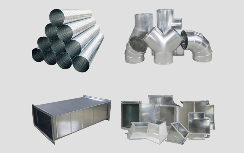
The sections for diversion, cones, branches, valves, vents, and equipment must be compared with the symbols and schedules. Do not rely solely on the illustrative shape to determine the structure if the drawing includes a separate detailed table.
4. Compare with architectural drawings and other disciplines.
Air ducts often pass through areas containing beams, ceilings, cable trays, water pipes, and fire protection equipment. Therefore, coordination drawings should be consulted to identify intersections and check installation clearances. Any inconsistencies should be clarified before production begins.
Summary table
| Information on the drawing | Need to read/compare | Application |
| Code and version | Release date, approval status | Choose the right production data. |
| Pipe size | Width, height, or diameter as indicated | Determine the specifications of the components. |
| Altitude | Elevation of the line and points of change | Coordinate installation space |
| Accessory symbols | Elbows, tees, cones, valves, air vents | Create an order list. |
| Technical notes | Material, thickness, specific requirements | Control the scope of machining |
Conclusion
The correct way to read HVAC ductwork drawings should be considered in conjunction with the design documentation, construction conditions, and acceptance requirements of each project. Agreeing on information from the outset helps contractors control quality, minimize issues, and facilitate more effective coordination among all parties.
Contact Sao Viet Air Ducting
Sao Viet Air Ducting accepts requests for fabrication of air ducts and accessories according to project drawings and technical documents. M&E contractors can submit drawings or Bill of Quantities (BOQ) to discuss the scope of supply and necessary confirmation information.
SAO VIET AIR DUCT MANUFACTURING AND TRADING COMPANY LIMITED
Address: 267 Le Thanh Tong, May Chai, Hai Phong
Hanoi Representative Office: No. 19, Lane 24, Kim Dong Street, Giap Bat Ward, Hoang Mai District, Hanoi
Hotline: 0815.999.826 – 0934.559.168 | Technical support: 0949.852.886
Email: vietonggio@gmail.com